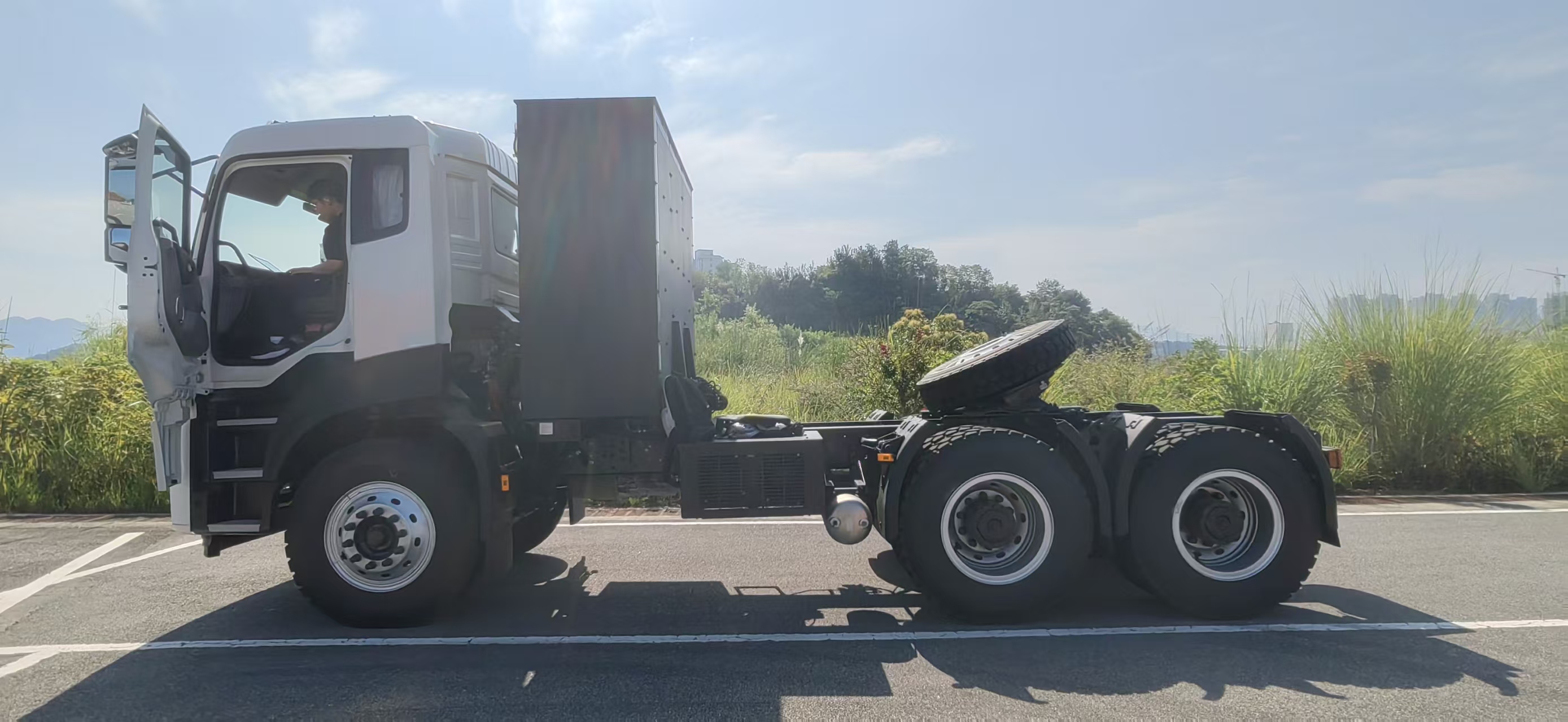
Start with a real chassis specification
Upfit engineering should start from the ordered vehicle's signed technical schedule, not a generic model-family brochure. The table below uses a customer-provided TE9Y 6×4 tractor worksheet as an example of information a project team can verify. It is a tractor reference, not a claim that this build is a body chassis or that a PTO is included. The worksheet does not state a PTO output, mounting interface, voltage, continuous power allowance or approved body-builder protocol.
| TE9Y worksheet item | Listed value | Upfit relevance / confirmation |
|---|---|---|
| Configuration | DFH4250YBEV8-TE9Y-902, 6×4 electric tractor | Confirm whether the actual order is a tractor or body-chassis variant |
| Gross combination weight | 120,000 kg listed GCW | Not body payload; validate complete combination and local limits |
| Kerb weight | 14,450 kg listed | Reconfirm with production options and equipment |
| Battery capacity | 600.92 kWh listed | Worksheet does not define usable energy available to auxiliaries |
| Drive motor | 315 kW rated / 510 kW peak listed | Traction ratings do not define auxiliary/PTO output |
| Charging entry | Dual-gun DC, 600 A listed | Confirm inlet, current basis, charge curve and site compatibility |
| Overall dimensions | 7,795 × 2,550 × 3,270 mm listed | Use final drawings for body clearances and installation |
These values come from the supplied configuration guide in this project. The missing PTO details are deliberate: no interface should be inferred from battery capacity or motor output. See the TE9Y configuration guide for its source and limitations.
Specify the chassis-to-body interface before ordering
Write down the work the vehicle must perform: material handled, required output, operating duration, start-stop frequency, peak demand, ambient conditions and the expected shift. Translate that duty into an equipment specification with the body builder. “PTO required” is not enough. The vehicle supplier and body builder should identify whether the equipment is mechanically driven, powered by a dedicated electric motor, supplied through an approved high-voltage interface, or supported by another documented arrangement.
For every proposed interface, request a drawing and a written interface-control document. It should identify mounting locations, allowable loads, voltage and current boundaries where applicable, protection and isolation, connectors, control signals, emergency stop behavior, interlocks, diagnostics and service access. State who supplies each component and who is responsible for integration approval. Do not let an installer tap into a traction circuit or modify high-voltage equipment without written manufacturer authorization and qualified personnel.
Also define the operating logic. Can equipment run while parked, while driving, or both? What prevents unintended operation? How is the driver informed of a fault? What happens to the body equipment during a vehicle shutdown, charging session or emergency isolation? These questions affect safety, productivity and supportability, and should be settled in the engineering review rather than after delivery.
Model auxiliary energy as part of the route
A battery-electric truck's traction system and its work equipment draw from finite energy resources, but the approved architecture varies by model. Ask the supplier how auxiliary consumption is measured, whether it is included in vehicle telemetry, and how the vehicle limits or protects the equipment. For a pump, crane, lift, compactor or refrigeration unit, estimate energy per cycle and energy per shift using the actual operating profile. Include idle periods, repeated starts, hydraulic demand and seasonal conditions.
Keep the calculation transparent: daily traction energy plus body-equipment energy plus thermal-management and cab loads, then a clearly stated operating reserve. Replace estimates with measured data during a pilot. Recheck charging windows and charger/site capacity if equipment use increases the energy needed between dispatches. The 600.92 kWh TE9Y worksheet figure is not a guarantee of usable energy or range with an auxiliary load.
Agree how operators should manage the body system at low state of charge, during a fault, or when the truck is charging. Set dispatch rules based on the vehicle manufacturer's guidance and the actual equipment integration. Do not promise a fixed operating time until the full vehicle has been tested under representative work.
Recheck mass, centre of gravity and packaging
Body weight affects tare mass, axle distribution, stability, available payload and—in a tractor application—the legal and practical combination configuration. Ask for the equipment's dry and operating mass, fluid or material mass, centre-of-gravity position, mounting loads and any dynamic forces. Recalculate front and rear axle loads for the complete vehicle at relevant operating states. Obtain the final upfit drawing and weigh the completed vehicle as required by the project approval pathway.
Check overall length, width and height, service clearances, cooling airflow, battery enclosure access, cab tilt, cable routing, articulation, turning envelope and maintenance access. For a tractor, validate fifth-wheel position and trailer clearance; a body installation may be inappropriate for a tractor chassis unless the manufacturer has approved a specific configuration. Confirm corrosion protection, fasteners, frame drilling restrictions and any no-modification zones from the chassis documentation.
Build destination-market requirements into the interface
Export projects need one coordinated approval path for the base vehicle and completed vehicle. Ask the importer, relevant authorities and qualified local engineering partner which documents, inspections, labels, electrical protections and vehicle classifications apply. Requirements vary by destination and equipment type. This guide does not certify the TE9Y or any upfit for Pakistan or another market.
Make the commercial order match the approved engineering scope: base chassis, body equipment, installation location, software or control work, testing, training, parts, warranty responsibilities and change control. Confirm whether modifications affect the vehicle warranty and who owns troubleshooting when a fault crosses the vehicle/body boundary. Require a signed acceptance procedure that covers both driving and stationary work modes.
Body-builder and buyer checklist
- Describe the application, shift pattern, output target and equipment duty cycle.
- Confirm chassis type and exact model code; do not treat tractor and body chassis as interchangeable.
- Obtain approved PTO or auxiliary-power documentation, interface drawings and operating limits.
- Record equipment power, energy per cycle, controls, interlocks, isolation and fault behavior.
- Submit body mass, centre of gravity, mounting loads and final installation drawings.
- Recalculate axle loads, complete-vehicle dimensions and energy use after upfit.
- Agree destination approval, tests, warranty boundaries, service training and spare parts.
- Run an instrumented pilot and document acceptance criteria before fleet rollout.
For a chassis/body compatibility review, send the application, equipment datasheet, duty cycle, target market and requested interface through the configuration enquiry page. Browse the special-purpose electric truck range and the charger compatibility checklist for related project checks.
Frequently asked questions
Does an electric truck automatically support a conventional PTO?
No. Confirm the approved chassis interface, available power, controls, operating limits and body-builder documentation for the exact build.
Does the TE9Y worksheet confirm a PTO?
No PTO output or body interface is identified in the supplied worksheet. Request written engineering confirmation; do not infer it from motor or battery figures.
Can I size an auxiliary system from battery capacity alone?
No. Use measured or validated energy consumption for the complete duty cycle, including traction, equipment, thermal loads and reserve.
BODY INTEGRATION
Planning a body or auxiliary system?
Share the chassis, body datasheet, operating cycle and destination market for a compatibility discussion.
Request a Configuration