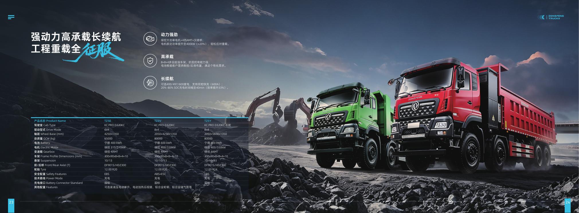
Energy-planning principle: calculate the full haul cycle from loaded travel, empty return, queueing, loading, dumping and auxiliary work. Grade, rolling surface, payload and charging windows all matter. The configuration below is a catalogue reference, not a measured mine-site range or payload rating.
Describe the mine duty cycle in operating terms
“Mine haulage” covers different missions: short loops between a loading face and crusher, longer quarry movements, underground haulage or mixed public-road routes. Start with the exact vehicle role. Record one-way and round-trip distance, elevation profile, sustained grades, surface, speed, stops, loading and dumping time, queueing, shift length and cycles per shift.
Use route segments rather than one average. A loaded climb, empty descent, flat haul road and crusher queue have different energy and time profiles. Mark road changes, ramps, rough or soft sections, water crossings, turning areas and safe waiting or charging locations. Survey the route with site management and document ordinary variations between shifts.
Payload must be treated carefully. Gross vehicle weight (GVW) describes the completed vehicle at its rated mass; payload is cargo carried within the approved mass and axle limits. Calculate it using the selected body, tare, load distribution and local rules. Never infer cargo capacity by subtracting a mass value from an unrelated catalogue row.
Use verified configuration data as a boundary
The project catalogue lists the Dongfeng TZ3Z as an 8×4 electric dump-truck reference with 55 t GVW and a 400 kWh battery. The entry supports initial model screening, but does not provide mine-route energy, payload, gradeability, cycle count or seasonal performance.
| Reference item | Listed information | Project validation needed |
|---|---|---|
| Model / layout | TZ3Z, 8×4 | Exact model code, destination build and site approval |
| GVW | 55 t | Completed tare, payload and axle distribution |
| Battery | 400 kWh catalogue configuration | Usable energy, SOC window and ordered pack |
| Duty evidence | No measured mine cycle in catalogue | Route energy, grades, loads and shift data |
See the TZ3Z quarry-haulage guide for model context. A specification is not a site performance result; request a build-specific assessment for the route.
Measure energy by segment and by cycle
Build the estimate from comparable instrumented operation or a controlled pilot. Log departure and return SOC, distance, energy delivered, payload, loaded and empty times, speed, elevation, ambient temperature, road condition, stops, auxiliary equipment use and charging interruptions. Tie each record to the truck, tyres, body, route and operator. Fleet averages can hide high demand on a sustained climb or rough haul road.
Sum measured energy for each segment and add measured stationary and auxiliary demand. Preserve the evidence behind each input. If measurements come from a different truck, disclose the difference and mark the number as an assumption. Avoid a single kWh-per-kilometre value when loaded and empty legs have different gradients or surfaces.
Compare expected shift demand with confirmed usable battery energy and a site-defined reserve. Do not plan to dispatch against every nominal kilowatt-hour. Reserve should cover realistic contingencies: route diversion, queue delay, a changed loading face, weather, reduced charger availability or a safe return to charging. Set SOC and dispatch thresholds with the vehicle supplier and site team.
Model grade, traction and downhill operation
For each important climb, record length, gradient, load, target speed, stopping points and traffic. Ask the supplier to review continuous motor and thermal limits for the actual combination. Peak motor output alone cannot establish sustained hill performance or cycle time. Check restart conditions on ramps and whether the road allows safe passing, queuing or recovery.
Downhill segments require a separate operating review. Regenerative braking is not a guaranteed energy credit or a replacement for the approved braking system. Recovery depends on the vehicle, state of charge, speed and conditions. Confirm operating instructions and braking strategy for long descents. Include safe speed, road condition, loaded mass, stopping distance and emergency arrangements in route approval.
Rolling resistance varies with the surface. Paved haul roads, compacted gravel, loose material and wet or rutted tracks should not share one assumed consumption rate. Document maintenance condition, dust and water exposure, tyre requirements, turning areas and restrictions on charging or parking in work zones.
Plan charging around loading and shift handovers
Draw production and charging schedules together. Note when the truck is available at a depot or site, how long it waits at loading and dumping points, whether that dwell is predictable and whether charging can happen safely without interrupting traffic. Opportunity charging helps only if the equipment is compatible, accessible and reliable.
Obtain the ordered vehicle's charge curve, connector, protocol, voltage, current limits and operating conditions. A qualified electrical professional should review supply, transformer, switchgear, protection, cables, environmental exposure, equipment protection and emergency access. Position chargers for safe vehicle movement and cable handling. Do not estimate charge duration by dividing nominal battery capacity by an assumed charger rating.
For several trucks, model arrival windows and simultaneous charging. A staggered plan may fit the shift better than adding chargers without checking the electrical system; future fleet growth should still be considered in site design. Assign responsibility for monitoring faults and dispatching a truck when a charger is unavailable.
Run a site pilot with production data
Agree on route, load, truck configuration, measurement method, reserve, charger access and success criteria in advance. Include the conditions that drive a demanding routine shift. Track completed cycles, site-measured tonnes or loads, energy per cycle, queue and loading times, availability, charging dwell, maintenance events and driver feedback.
Compare results with the site baseline and separate vehicle performance from production bottlenecks. If the loading face, dump point or route changes, update energy and schedule assumptions. A demonstration shift does not prove annual output or all-season performance. Expand in stages when route, charging and support plans have repeatable evidence.
Mine-site electric truck checklist
- Route map with segment distance, elevation, grade, surface and safe stopping points.
- Loaded and empty mass, payload method, axle loads and approved body configuration.
- Shift length, cycles, loading time, dumping time, queues and handover schedule.
- Measured energy by route segment, usable energy and dispatch reserve.
- Grade, thermal, braking and traction review for the selected build.
- Charger compatibility, electrical survey, protection and fault response.
- Site access, operator training, service support and parts plan.
- Controlled pilot and evidence before fleet expansion.
Submit the route, grade profile, payload basis, shift plan and charging location through the configuration enquiry page. U.S. DOE fleet planning guidance also recommends evaluating route, terrain, weather, auxiliary demand and charging needs.
Frequently asked questions
Does 55 t GVW mean a 55 t payload?
No. GVW applies to the completed vehicle, not cargo. Confirm tare, body, axle loads and site limits.
Can a 400 kWh entry tell me trips per shift?
No. Use measured route energy with loaded mass, grades, surface, dwell and reserve.
Can downhill regeneration be a fixed energy credit?
No. Confirm vehicle operating limits and measure actual recovery on the intended route.